MAJORITY VOTE
Project Overview
For this project we designed a circuit and logic expression to create a fair system for voting between a President, Vice President, Secretary, and Treasurer. A majority vote always wins, but in the event of a tie the president's decision conquers. The design was limited to two-input gates only. Below is the process of developing the truth table, logic expressions, and circuit.
Problem Conception via Truth Table & Un-simplified Expression
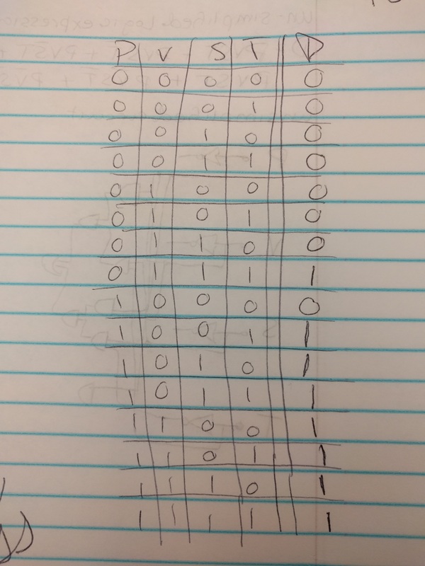
The truth table is used to demonstrate all the possible voting combinations and the result of each. The number of rows is equal to 2 raised to the number of variables. In this case there are four variables, which results in 16 rows. Each 1 in the P,V,S, and T (President, Vice President, Secretary, and Treasurer) columns represents a yes vote, while a 0 represents a no vote. The D column represents the decision, 1 being a final yes and 0 being a final no. Each row with a majority yes results in a final decision being yes. In the event of a tie, the President's vote is used to break the tie.
|
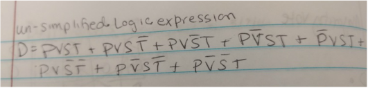
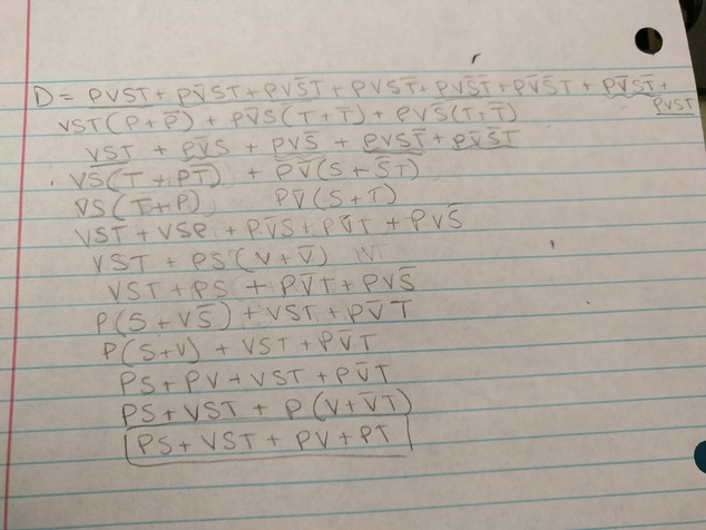
The un-simplified logic expression is in the sum of products (SOP) form. The minterms were found using all the combinations resulting in a yes (1) final decision. Every row resulting in a 1 is added to the expression because that is a possible combination (OR). Each variable in a row is multiplied together because they rely on each other (AND). SOP form was used because it is easy to convert the results from the truth table to a sum of products expression.
|
Un-simplified Circuit
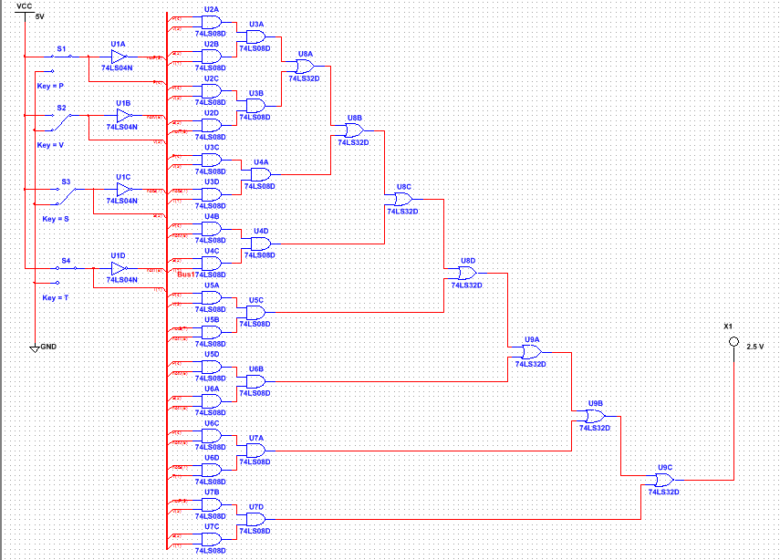
This is the un-simplified circuit for the logic expression using a bus to organize the wires. This circuit uses 4 invertor gates, 24 AND gates, and 7 OR gates. This circuit is very tedious and complex. Precision is needed to correctly assemble the circuit, even with the bus. Making this circuit with a breadboard would only be more complicated. 1 invertor chip, 6 AND chips, and 2 OR chips would be required. This complexity is unnecessary because, using Boolean algebra. it can be simplified.
Boolean Algebra
Using Boolean Algebra I was able to simplify the original logic expression into the one below.
D = VST + PV + PS + PT
Simplified Circuit
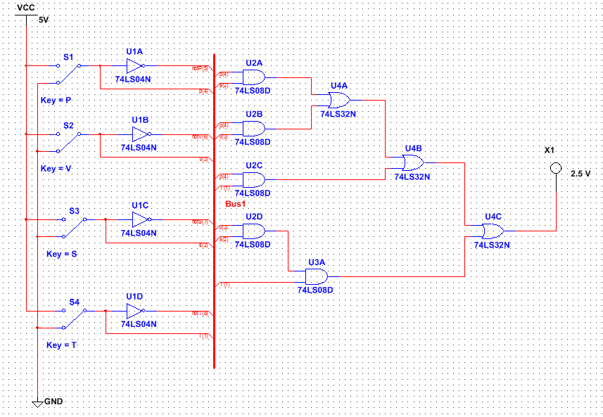
The simplified circuit is also in bus form to promote organization. This circuit only requires 5 AND gates and 3 OR gates, which is much less than the un-simplified expression. Invertor gates are visible in the circuit schematic, but none are actually used. 2 AND chips and 1 OR chip would be required to transfer the circuit to a breadboard. Four gates are in every chip, which means you can determine the number of chips required by dividing the number of gates required by four. When transferring the circuit to a breadboard a resistor is used before the LED to prevent it from burning out.
This is a simplified version of the logic expression because it gives the same results but with fewer gates and components. The simplified circuit contained 4 fewer invertor gates, 19 fewer AND gates, and 4 fewer OR gates. The simplified breadboard would contain 1 fewer invertor chip, 4 fewer AND chips, and 1 fewer OR chip. It is important that the simplified expression has less components because it is much easier to understand and build, while also resulting in a lesser cost. Simply building the un-simplified circuit would result in so much confusion and chaos that the circuit would very likely not work.
This is a simplified version of the logic expression because it gives the same results but with fewer gates and components. The simplified circuit contained 4 fewer invertor gates, 19 fewer AND gates, and 4 fewer OR gates. The simplified breadboard would contain 1 fewer invertor chip, 4 fewer AND chips, and 1 fewer OR chip. It is important that the simplified expression has less components because it is much easier to understand and build, while also resulting in a lesser cost. Simply building the un-simplified circuit would result in so much confusion and chaos that the circuit would very likely not work.
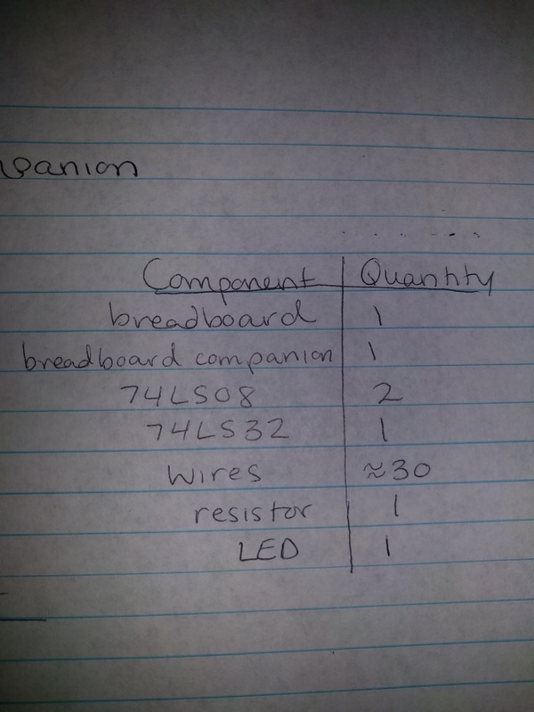
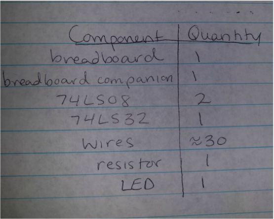
Bill of Materials
This table demonstrates each component used for the simplified breadboard and the quantity of each component.
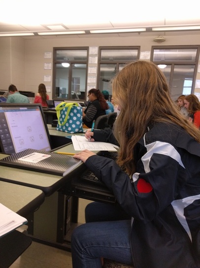
Bread-boarding
|
|
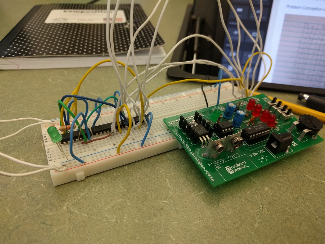
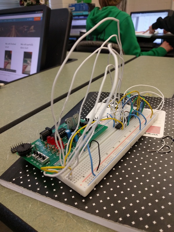
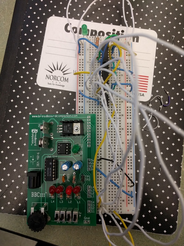
These pictures show the breadboard of the simplified logic expression from different angles and distances.
This bread-boarding experience was not too difficult, but did require some thought. The closeness of the wires and components resulted in some confusion while assembling. I did learn how to use only 2 input gates efficiently to make a more complex circuit. My circuit did not originally work and after numerous inspections I could not find the issue. The issued was that two wires were accidently touching, throwing the whole circuit off. This is also made me learn that even the slightest imperfection can result in a faulty circuit.
This bread-boarding experience was not too difficult, but did require some thought. The closeness of the wires and components resulted in some confusion while assembling. I did learn how to use only 2 input gates efficiently to make a more complex circuit. My circuit did not originally work and after numerous inspections I could not find the issue. The issued was that two wires were accidently touching, throwing the whole circuit off. This is also made me learn that even the slightest imperfection can result in a faulty circuit.
Conclusion & Reflection
Throughout this project I learned how truth tables, logic expressions, and schematics interact to form a fully functioning circuit from a problem statement. By dissection a problem statement you can create a truth table and a logic expression. From there Boolean Algebra can be used to create a simplified logic expression and a simplified circuit. Boolean Algebra is useful because it can turn a logic expression that requires many gates to an expression that only requires a few. In this project Boolean Algebra was used to decrease the number of AND gates from 24 to 5. This greatly reduced the complexity and cost of the circuit, while still having the same results. I thought this was one of the most impressive aspects of this project. It demonstrated the importance of each step in the process of converting from problem statement to logic expression to truth table to logic expression to simplified logic expression to eventually an actual circuit. This project also demonstrated a real life application of truth tables, logic expressions, and circuits. The real life application made the process more understandable, especially the Boolean algebra. I was able to see how the simplified expression was derived from the problem statement and the un-simplified expression. Overall I liked this project because it walked through every step of the process and allowed me to better understand it.