TRUSS DESIGN
For our third "Principals of Engineering" project we were asked to build and test 3 truss designs. We built the trusses using balsa wood and craft glue. We then tested the maximum force the trusses could hold.
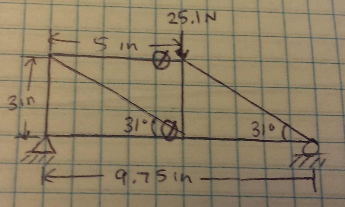
Sketch of Truss 1
Sketch of Truss 2
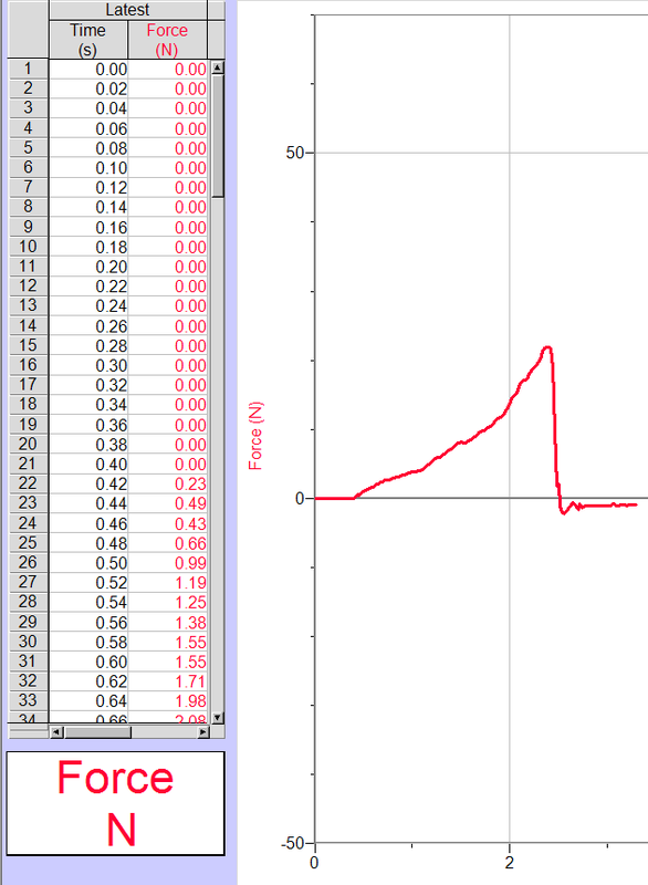
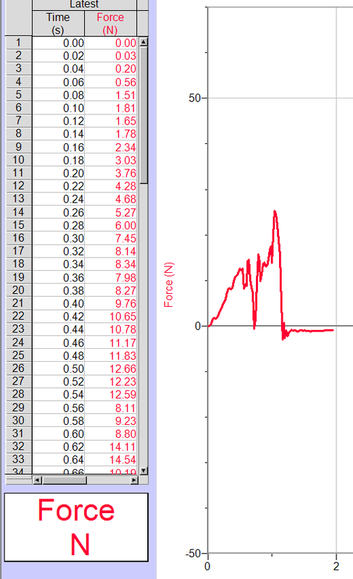
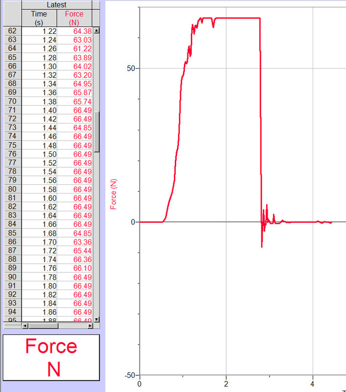
Graphs
|
Truss 1
|
Truss 2
|
|
|
Videos of Testing
|
|
|
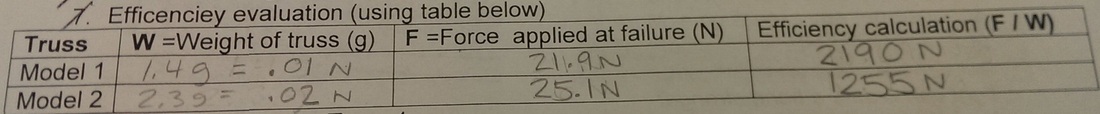
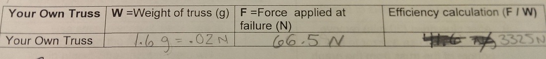
Efficiency Evaluation
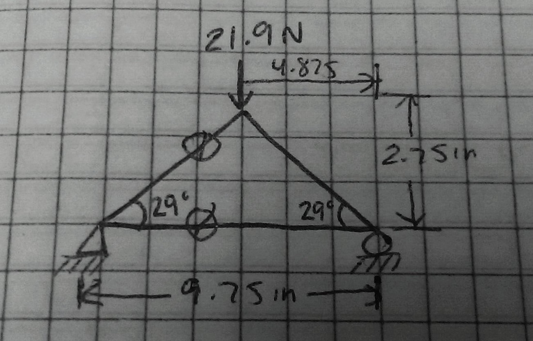
Truss Calculations for Truss 1
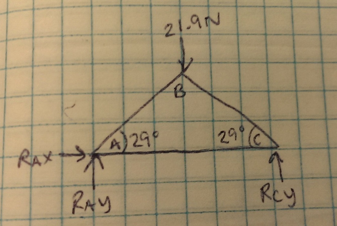
a) Free Body Diagram
b) Staically Determinate?
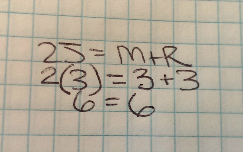
Truss 1 is statically determinate.
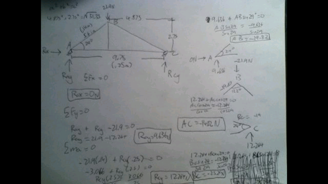
c) Reaction Forces
RAX= 0 N
RAY= 9.636 N
RCY= 12.264 N
RAY= 9.636 N
RCY= 12.264 N
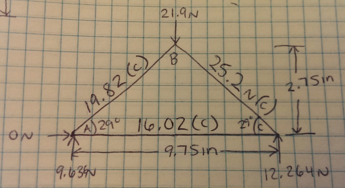
d) Tension or Compression Forces in Each Member
e) Final
Truss Calculations for Truss 2
a) Free Body Diagram
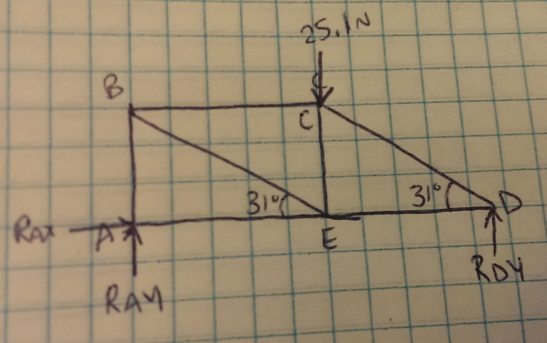
b) Statically Determinate?
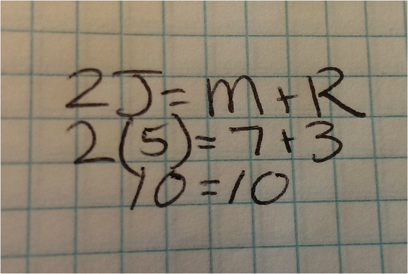
Truss 2 is statically determinate.
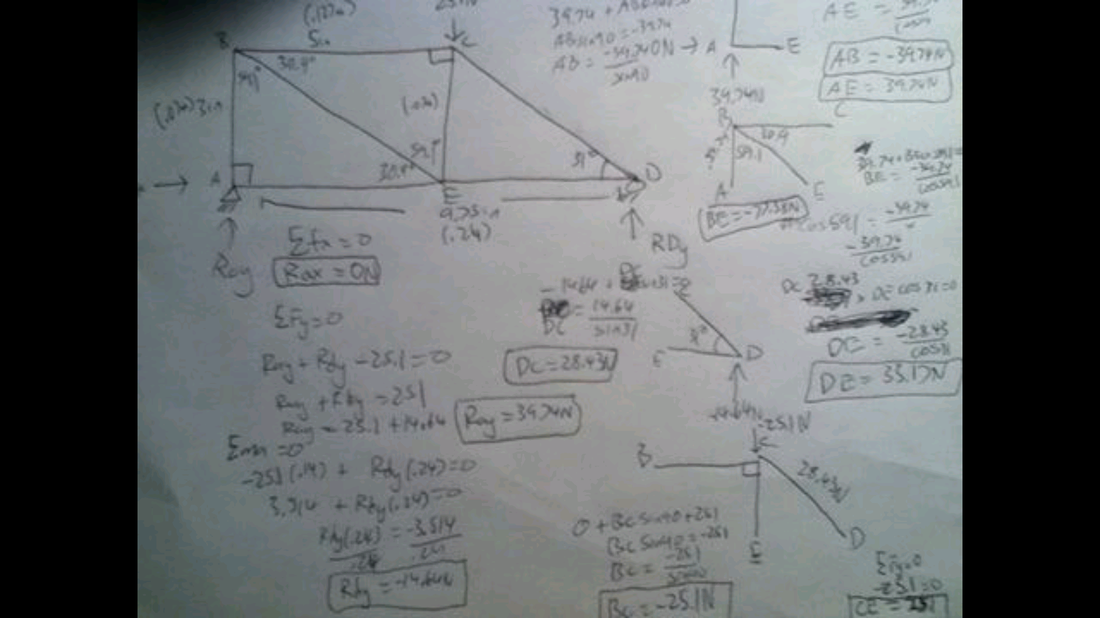
c) Reaction Forces
RAX= 0 N
RAY= 34.7 N
RDY= -14.6 N
RAY= 34.7 N
RDY= -14.6 N
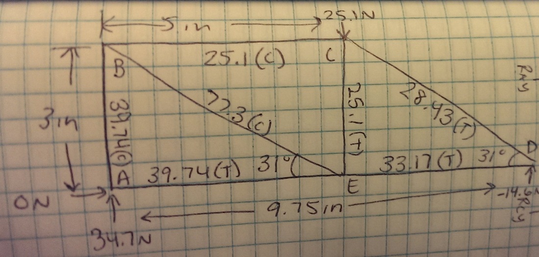
d) Tension or Compression Forces in Members
e) Final
Truss Calculations for Our Truss
a) Challenge and Constraints
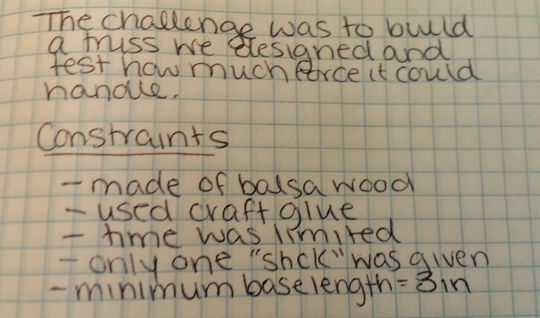
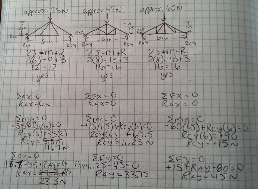
b) Three Possible Solutions
|
Design #1
|
Design #2
|
Design #3
|
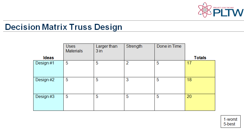
c) Decision Matrix
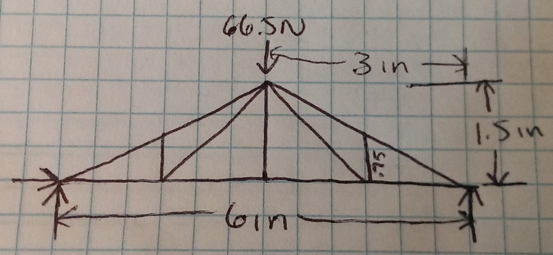
d) Sketch of Final Design
e) Calculations of all Forces
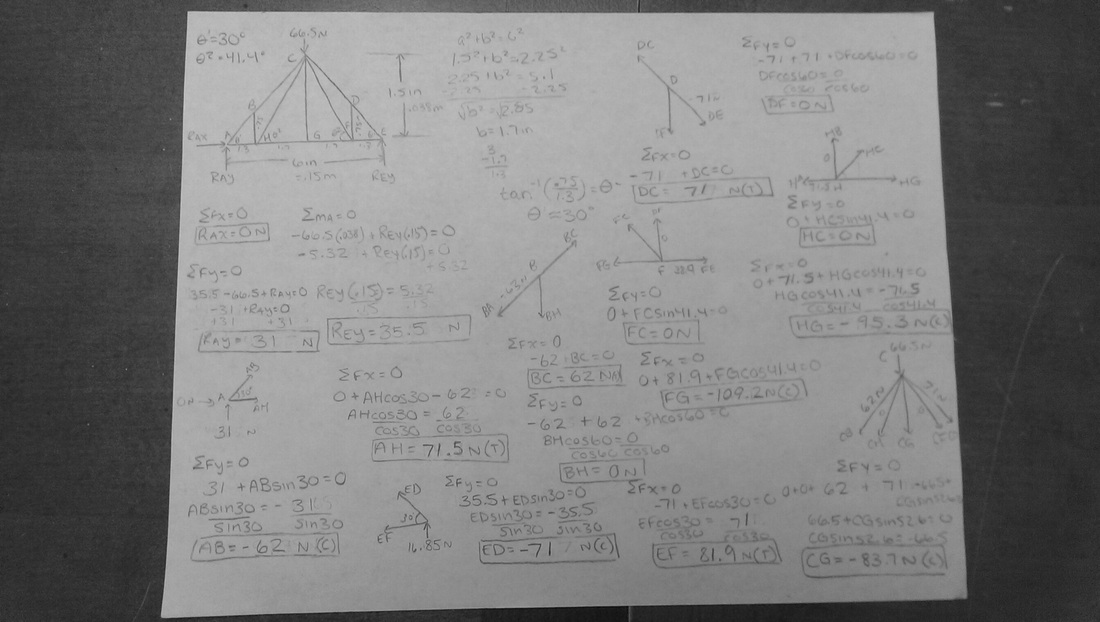
f) Evaluate Efficiency
Conclusions
11. I think the truss failed where it did because the member was expiriencing high levels of tension. My calculations showed that the member that failed (BC) did not expirience the most tension but it was the second largest and was closer to the applied force.
12. After testing I would have included more right angles. More right angles would have made the truss stronger.
|
|
|